IFC Viewer Online · Back to the BIM & IFC blog
Validation & quality · 2026-11-18 · 8 min
As-Built vs BIM: Checking a Point Cloud Against the IFC Model, Element by Element
Comparing a scan with the model sounds simple: measure the distance, colour it. The hard part is being honest about what the scan did not see. The method step by step, and a preview of the as-built check we are building.
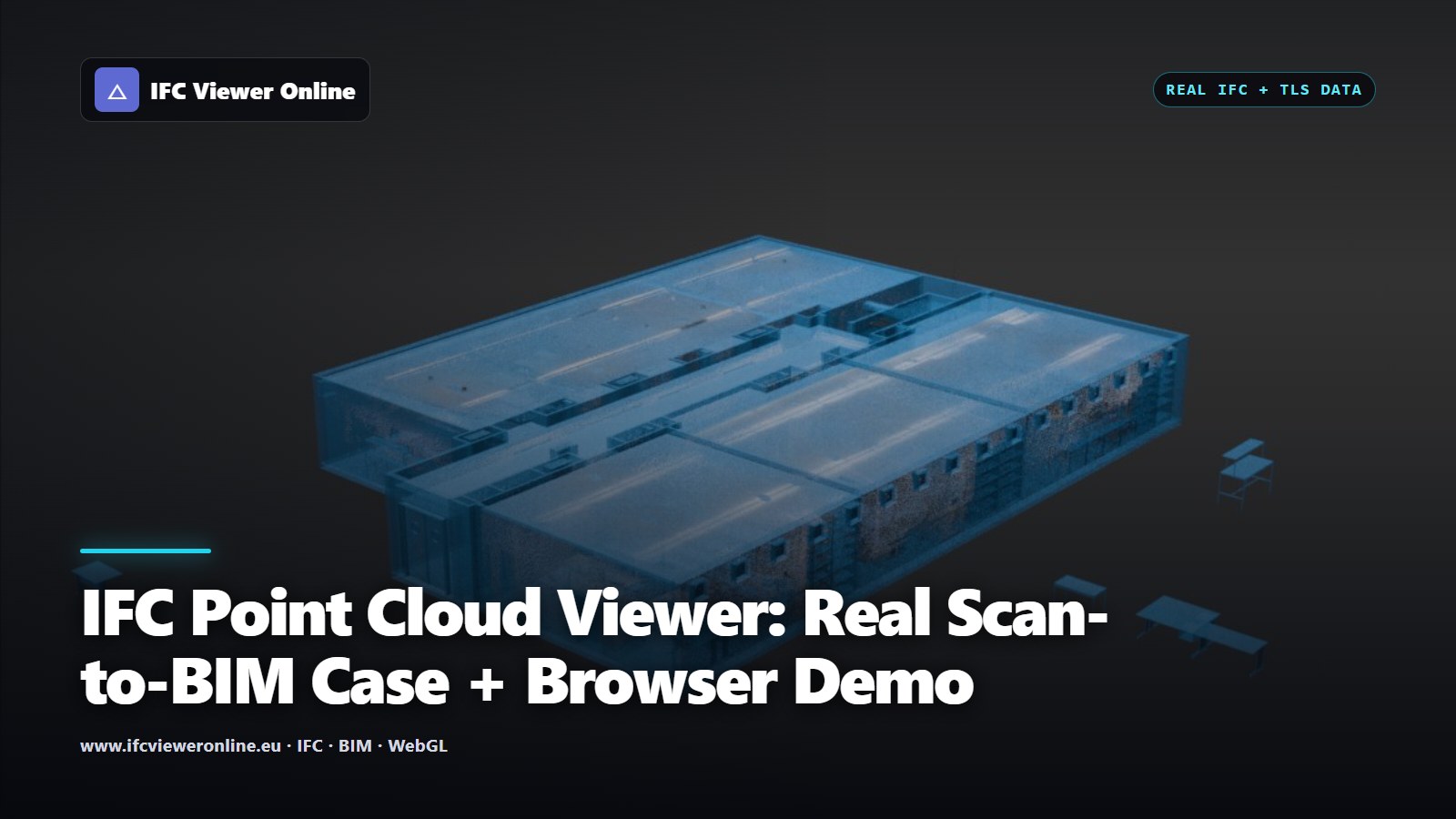 A laser scan of a building loaded together with its IFC model in IFC Viewer Online
You have the IFC model of a building and a scan of what was actually built. The question on site is plain: was it built where it was drawn? The usual answer is a colour map of distances between the two. It looks convincing, and it can be wrong in a way nobody notices: everything the scanner did not see shows up as if it were fine.
This article explains how an as-built check works when it is done honestly: alignment first, a tolerance that means something, and a clear line between "built as modelled", "built elsewhere", "not built" and "not seen".
Key takeaways
- Align the scan with the model before measuring anything. A misaligned scan looks exactly like a badly built building.
- The tolerance has to be larger than the error of the scan plus the error of the alignment, or you are measuring your own setup.
- Each element is either conforming, deviated, missing, or not observed. Not observed is not the same as conforming.
- A result always comes with its coverage: the share of the model the scan could actually see.
Step 1: get the scan and the model in the same place
A laser scanner exports E57 or LAS/LAZ[e57] [las], usually in the surveyor's coordinates. A phone LiDAR scan has its own local origin. The IFC has its own placement, and sometimes a georeference. Before any distance means anything, the three have to be brought into one coordinate system.
The robust way is to pick at least three points that you can recognise in both, such as column corners, slab edges or the corner of a stair, and fit the transformation between them. The fit leaves a residual error (the RMSE of the alignment). Write it down: it limits everything that follows.
Step 2: choose a tolerance that can be measured
The tolerance has two parts. One is the construction tolerance you are checking against: for example 25 mm for a structural element, which is a common starting point, but the contract or the project specification decides. The other is the uncertainty of the measurement itself: the accuracy of the scanner, and the RMSE of the alignment.
The rule we use: if the tolerance is not clearly larger than the alignment error (we require at least twice), the check refuses to give a result and says why. Without that rule, a tool produces confident deviation reports that are artefacts of the registration.
| Source of the scan | Typical use | What it is good for |
|---|
| Terrestrial laser scanner (E57, LAS) | Surveys, structure, facades | Tight tolerances, if the registration is good |
| Phone or tablet LiDAR | Rooms, quick checks on site | Finding missing or misplaced elements, not millimetres |
| Point cloud from a video | Walk-through of a site | Coarse checks; accuracy depends on the reconstruction |
A rough guide, not a specification. Check the accuracy your own device and workflow achieve before setting a tolerance.Step 3: compare element by element, not point by point
A colour map of point distances answers "how far is this point from the nearest surface". A construction team needs a different answer: "is this wall where it should be". So the comparison starts from the model. The surface of each IFC element is sampled into points, and for every sample the nearest scan point is found. Then each element gets one of five states:
| State | When | What it means |
|---|
| Conforming | Matched, and 95% of its samples within tolerance | Built where the model says |
| Deviated | Matched, but beyond tolerance | Built, but in the wrong place or with the wrong size |
| Missing | Seen by the scan, but less than 20% of it matched | Modelled and not built (or not built yet) |
| Not observed | No scan position could see it | Unknown: it cannot be scored |
| Occluded | In view, but hidden behind something | Unknown: it cannot be scored |
There is also the opposite direction: scan points with no IFC element near them. Grouped together, they are things that were built but not modelled. That is often the most useful finding on site, and no IFC validator can produce it, because it needs the reality.
Step 4: report coverage next to the result
This is the part most tools skip. If you scan one clean corner for twenty seconds and count everything else as fine, you get a perfect score for a building you never looked at. So an element that was not observed is neither conforming nor non-conforming. It is unknown, and it is counted separately.
The result is therefore always two numbers, never one: how well what was seen matches, and how much of the model was seen. A good match over a small share of the model is not a conclusion. Our rule is that below 25% coverage there is no score at all, only "capture insufficient".
Why one problem should not count a hundred times
If a whole slab was poured 4 cm high, that is one problem on site, not eight hundred defective elements. The score uses the same logarithmic penalty as our Health Score for IFC models: many elements with the same issue weigh more than one, but not proportionally. Otherwise any real capture would score zero and the number would be useless.
What you can do today, for free
Load the IFC and your scan together in the viewer: E57, LAS/LAZ and other common formats open in the browser, without uploading anything. How that works on a real scan-to-BIM case is in IFC and point clouds in the browser.
For a first answer to "is this wall where it was drawn", slice the scan at a height and compare it with the plan cut from the model: check a point cloud against the IFC floor plan. It is a 2D check at one height, so it finds where to look rather than certifying anything. For floors, slab flatness from a point cloud works the same way.
What the as-built check will add, and what it will cost
| Free (in the browser) | Paid plan (planned) |
|---|
| Your own point cloud (E57, LAS/LAZ, phone LiDAR) | Yes: per-element states, coverage and score, computed on your computer | Same |
| A phone video turned into a point cloud | No | Yes: the video is processed on a graphics server |
| Your IFC model | Never leaves the browser | Never leaves the browser: only the video is sent |
Plan for the feature, not a promise of dates. Planned prices are on the pricing page.The split follows one rule: anything that costs us money to run goes into the paid plan, and the free plan gets the version that runs on your own machine. Processing video needs a GPU server; comparing a point cloud you already have does not.[pricing]
What it does not do yet
- There is no interface yet: the comparison engine (sampling, nearest neighbour, visibility and score) is built and tested on synthetic scenes only.
- The three-point alignment is not built. Until it is, no score will be shown to users.
- It has not been tested on a real construction site by a customer.
If you check as-built work against IFC models and want to try it on a real project when it opens, tell us on the pricing page. For progress over time rather than conformance, see 4D construction progress with IFC and point clouds.
As-Built vs BIM: Checking a Point Cloud Against the IFC Model, Element by Element