Back to the BIM & IFC blog
Digital twins · 2026-08-21 · 11 min
IFC Point Cloud Viewer: Real Scan-to-BIM Case + Browser Demo
See a real CRAS TLS-to-IFC alignment, inspect sections and launch an interactive IFC + LAS browser demo with no model upload.
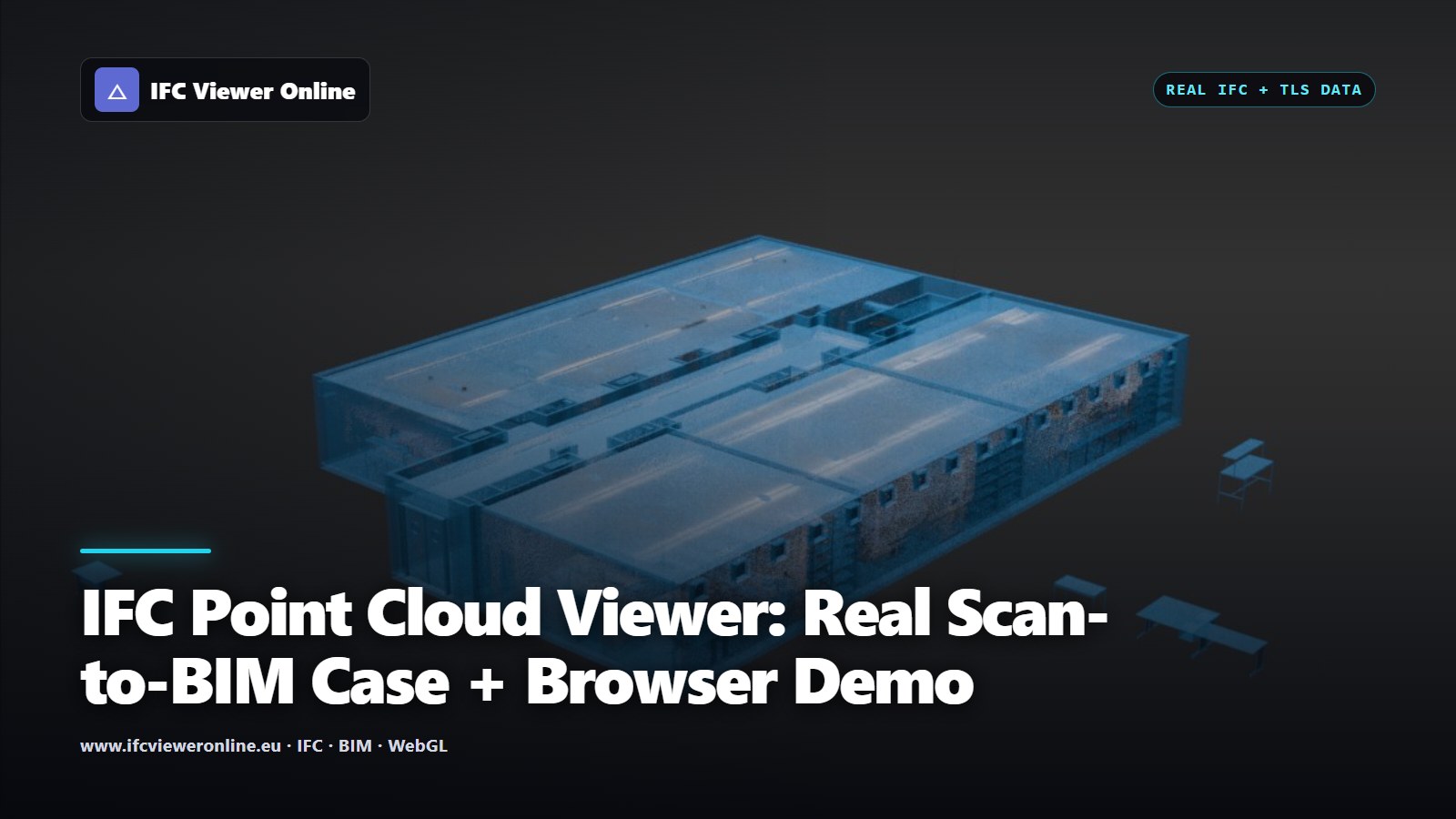 Cover titled IFC Point Cloud Viewer over a real CRAS Labs TLS point cloud aligned with its IFC model
Putting an IFC model and a point cloud in the same WebGL scene is visually impressive. Making the comparison defensible is a different job. A useful Scan-to-BIM viewer has to preserve source units, identify the up axis, resolve coordinate systems, expose any manual transform and keep enough points on screen to reveal deviations without exhausting the GPU.
This guide separates those concerns. The live example below uses a small synthetic pair for a fast exhibition experience; the validation images use a real terrestrial laser scanning dataset so that a concept illustration is never presented as survey evidence.
- 7 — supported point formats
- 999491 — points in the CRAS web sample
- 3 — alignment confidence levels
- 0 uploads — required for local files
Try IFC + a Point Cloud Live
Start the example to load a lightweight IFC4 pavilion and its matching LAS survey in the real viewer. Orbit the scene, inspect the overlay and open the full viewer if you want the complete point-cloud controls. This pair is synthetic and uses a shared ETRS89 / UTM 31N reference; it demonstrates the workflow, not the accuracy of a physical instrument.
Poblenou Pavilion — IFC + LAS overlay
Interactive browser example using a bundled IFC4 pavilion and a 150,000-point synthetic site survey with a shared projected CRS.
 IFC and LAS are ready — drag to orbit
What Alignment Actually Means
IFC can declare a projected coordinate reference through map conversion data. A point cloud may carry an EPSG code, local survey coordinates or no reference at all. When both sources declare the same CRS, placement can be exact in the mathematical sense. When they do not, the viewer needs a documented transform and must label its confidence. The buildingSMART IfcMapConversion definition describes the coordinate operation on the IFC side.
| Alignment rung | Evidence | What the UI should say |
|---|
| Exact | Common declared CRS and valid map conversion | Aligned by shared coordinate reference |
| Inferred | Compatible units, axes and geometry bounds | Probable placement — verify against control |
| Manual | User translation, rotation and scale | Placed manually — not survey control |
A confidence label prevents a convenient visual overlay from being mistaken for surveyed truth. Real Scan-vs-BIM alignment: the CRAS Labs TLS web sample over the unmodified IFC model.
A Browser Pipeline That Survives Large Scans
The browser should never assume that file size equals resident GPU size. Headers are inspected before allocating. The parser applies a point budget, workers keep decoding off the UI thread, and the renderer stores only the attributes the current display mode needs. For spatially indexed COPC or 3D Tiles, the camera selects visible nodes instead of downloading the whole survey.
OGC describes 3D Tiles as a hierarchical standard for streaming massive geospatial content including BIM/CAD and point clouds. That hierarchy is the important idea: screen-space error and view selection decide what to load. See the official OGC 3D Tiles overview.
Keep a local origin
Global coordinates stay in Float64 metadata; GPU vertices remain small local values to avoid visible jitter.
Budget points, not files
A declared count and a resident count are different facts. Show both when sampling or truncation occurs.
Reuse GPU attributes
RGB, intensity, classification and deviation views should share buffers instead of cloning the cloud.
Stream indexed formats
COPC or tiled data lets the camera request spatial nodes while a plain LAS file remains a one-shot decode.
 A section makes offsets easier to inspect than an attractive perspective view.
How to Present It at a Fair
- Begin with IFC only so the audience understands the designed geometry.
- Reveal the scan at medium opacity and explain the alignment confidence before discussing deviations.
- Switch to a section or deviation colour mode; do not rely only on a photogenic perspective.
- Pick one point and show source coordinates, classification and distance to make the scene operational.
- Finish by loading the offline bundled example again: a repeatable demo is more persuasive than venue Wi-Fi.
The same viewer can also handle time rather than only space. Continue with the real-time LiDAR architecture and MCAP replay guide, or add visual project evidence with IFC video placed on 3D terrain.
IFC Point Cloud Viewer: Real Scan-to-BIM Case + Browser Demo